In this tutorial, we present how to specify a high-voltage coupling system with ScenarioTools. It is an example from the automotive domain that was elaborated in collaboration with IAV Automotive Engineering, also see the following publication and Bachelor thesis (in German). Here we revisit a simplified variant of that example for the purpose of a tutorial.
What you will learn in this tutorial
- How to model simple informal requirements as scenarios using SML
- and how introducing more detail may be necessary in the formalization
- Understand the purpose and workings of assumption scenarios to model the
behavior of the system’s environment - employ play-out simulations to validate the specified behavior
- employ realizability checking to find inconsistencies
- what can help you detect, understand, and resolve inconsistencies
System overview
The following figure shows a sketch of the high-voltage coupling system (HVCS in the following). The system shall allow users to connect consumers to the high-voltage system of electrical or hybrid cars. An example would be to connect a high-power cooling system of a cooling trailer into the HV system of a hybrid truck.
The system requires a software-controlled interlock mechanism that prevents that users unplug consumers under load. This is because these systems can operate at high voltages of up to 400 or 600 Volt and unplugging under load can lead to dangerous lightning arcs that can injure or kill the user.
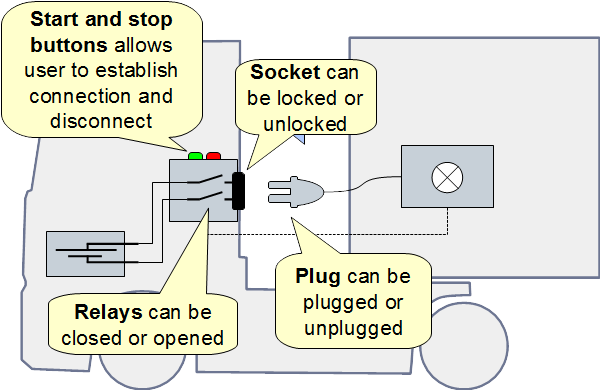
high-voltage coupling system (HCVS) overview
The HCVS consists mainly of an interface with a socket into which a plug can be plugged and from which the plug can be unplugged. The socket can be locked so that unplug is not possible. Furthermore, the interface has relays that can be closed and opened which closes or opens the power circuit. The interface also has a start and a stop button. The start button allows the user to establish a connection by closing the relays. This must only happen when the plug is plugged in and the socket is locked. The stop button interrupts the circuit by opening the relays and it unlocks the socket so that the plug can be unplugged.
Our objective is to specify the behavior for a central software controller that runs on a microcontroller embedded in the HCVS interface.
Example requirements
Let’s consider the following four example requirements for the process of plugging in a consumer into the socket and establishing a connection.
Object model (modeling the system structure)
From the explanations of the system and the sketch above, we first model the structure of the system. Also we have to clarify which components are controllable, i.e., software components to be developed, and which ones are uncontrollable, i.e., environment entities, or sensors and actuators.
We create the structure as shown in the following figure.
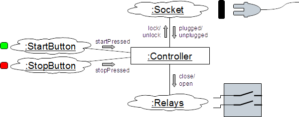
HVCS object model and events
The figure shows the central software controller component as the single controllable object. The socket, relays, and the start and stop buttons are uncontrollable (visualized by the cloud shape). We can also think about the events or messages exchanged by the objects. For example, the buttons are sensor components, which can notify the controller when the start or stop buttons are pressed. The relays object is an actuator: the software controller can order the relays to close or to open. The sockets is a combined sensor and actuator component that can, on the one hand, notify the controller of plug or unplug events. On the other hand, it is also an actuator, because the software component can order the socket to be locked or unlocked.
ECore class diagram
In ScenarioTools, we model this structure by, first, modeling the classes using an Ecore class model. Then we create an instance of this class model that corresponds to the system structure illustrated above.
The Ecore class model is shown below.
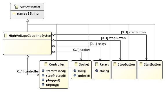
Diagram of the Ecore class model for the HVCS
Because we will have to refer to objects by their name later on, it is important that each class has a name attribute of type String. The easiest way to achieve this is to have an abstract class NamedElement that each other class inherits from. Furthermore, when working with EMF, its best when each model has a single root element that contains, directly or indirectly, all other elements. To achieve this in our example, we create the class HighVoltageCouplingSystem that can contain a controller, socket, relays, and start and stop button.
EMF object model
An instance of this system can be created using the EMF tree editor. The result looks as follows:
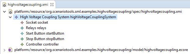
HVCS object model in the EMF tree editor
Also note that the classes above already define operations that correspond to events that their instances can receive. The SML specification will refer to these operations. If we need other events later, then we can always return to the class model and add more operations, or add then on-the-fly while editing the SML specification.
Modeling the first requirements with SML
We now create an SML specification with a our first two scenario that models the requirements r1 and r2.
The listing below shows the SML specification. Let us go through it line by line:
- line 1: Imports the Ecore model file that contains the Ecore class model described above.
- line 3: Defines the system specification for the HVCS.
- line 5: Defines a domain package, which is a package from the imported Ecore model that contains the classes that this SML specification refers to.
- lines 7-11: Defines which classes of objects are controllable and which are uncontrollable. In our example only the software controller is controllable, see the object model sketch above.
- line 13: Defines a collaboration
PlugAndStart. A collaboration defines how objects in the system collaborate to accomplish some desired behavior. For this purpose, a collaboration defines roles that represent objects in the system. A collaboration also contains scenarios that describe valid sequences of message events between the objects, i.e., what may, must, or must not happen in the system. A specification can contain multiple collaborations that can structure the specification according to use cases or features of the system. Here we define a collaborationPlugAndStartto contain the scenarios involved in the process of connecting a consumer to the HVCS. Later, we could add further collarations for example for the process of disconnecting a consumer from the HVCS and other possible features of the system. - lines 15-18: Here the collaboration defines the roles. In this case, the collaborations are static, which means that each role represents exactly one object in the system. As we will see shortly, this one-to-one mapping to object in the object model is specified in an additional configuration model. Roles can also be dynamic and bind to different objects depending on events and object properties that can change at run-time. We only need static roles here, since we have also have a static system structure.
- lines 20-27: Here we see the scenario modeling the requirement r1. This scenario says that when the socket notifies the controller that a plug was plugged in, then the controller must order the socket to lock.
- lines 33-36: Here we see the scenario modeling the requirement r2. This scenario says that when the start button notifies the controller that start was pressed, then the controller must order the relays to close.
import "../model/highvoltagecoupling.ecore"

system specification HighvoltagecouplingSpecification {

	domain highvoltagecoupling

	define Controller as controllable
	define Socket as uncontrollable
	define Relays as uncontrollable
	define StartButton as uncontrollable
	define StopButton as uncontrollable

	collaboration PlugAndStart {

		static role Socket socket
		static role Relays relays
		static role StartButton startButton
		static role Controller controller

		/*
		 * When the plug is plugged into the socket,
		 * then the socket must be locked.
		 */
		specification scenario WhenPluggedThenLock{
			message socket->controller.plugged()
			message strict requested controller->socket.lock()
		}

		/*
		 * When the start-button is pressed,
		 * then the relays have to be closed.
		 */
		specification scenario WhenStartPressedThenCloseContact{
			message startButton->controller.startPressed()
			message strict requested controller->relays.close()
		}

	}

}
In a bit more detail, the semantics of the scenarios and the messages appearing in it are as follows:
- specification scenario: Specification scenarios describe properties that the system must satisfy. As we will see, there are also assumption scenarios that describe properties that we assume will be satisfied by the environment that the system operates in.
- message: all events in the system are modeled as synchronous messages between a sender and receiver object. A scenario is activated when a message sending event (message event or only event in short) occurs in the system that corresponds to the first message in the scenario. We also say that an active copy of the scenario or active scenario is created. After activation, the second message is enabled in the active scenario. If an event occurs in the system that corresponds to an enabled message in an active scenario, the active scenario progresses and the subsequent message is enabled. The active scenario terminates if there is no further message to enable.
- strict message: when a strict message is enabled, this means that as long as this message is enabled, no message event must occur in the system that corresponds to another message in the same active scenario that is not currently enabled. Strict messages therefore allow us to specify safety properties.
- requested message: When a requested message is enabled, this means that a corresponding event must eventually occur, i.e., it must not be that the active scenario waits forever for the message event to occur. Requested messages therefore allow us to specify liveness properties.
First play-out simulation
The specification is obviously incomplete yet, but we can already execute and simulate the behavior described by the two scenarios. For this purpose, we must first connect the specification to the object model. As mentioned above, we need to define which role corresponds to which object in the object model. This configuration happens in run configuration model, which is shown in the listing below.
Run configuration model
The run configuration first loads an SML specification resource (line 1, via a relative or absolute path) and then defines the specification in that resource that shall be configured (line 2). Next, it defines a path to the object model that shall be used (line 4). This would be the model shown above. Last, it defines the role binding for roles in the specification’s collaborations that define static roles. Since our example specification only has one collaboration, we only define the role bindings for this collaboration (lines 6-11).
import "highvoltagecoupling.sml"
configure specification HighvoltagecouplingSpecification

use instancemodel "highvoltagecoupling.xmi"

rolebindings for collaboration PlugAndStart {
	object  highVoltageCouplingSystem.socket plays role socket
	object  highVoltageCouplingSystem.relays plays role relays
	object  highVoltageCouplingSystem.startButton plays role startButton
	object  highVoltageCouplingSystem.controller plays role controller
}
Interactive Simulation
We can then start a play-out execution of the run configuration as shown in the screenshot below:
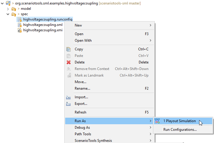
Starting a play-out simulation
When we play out the different events that are possible, we quickly see the following picture:
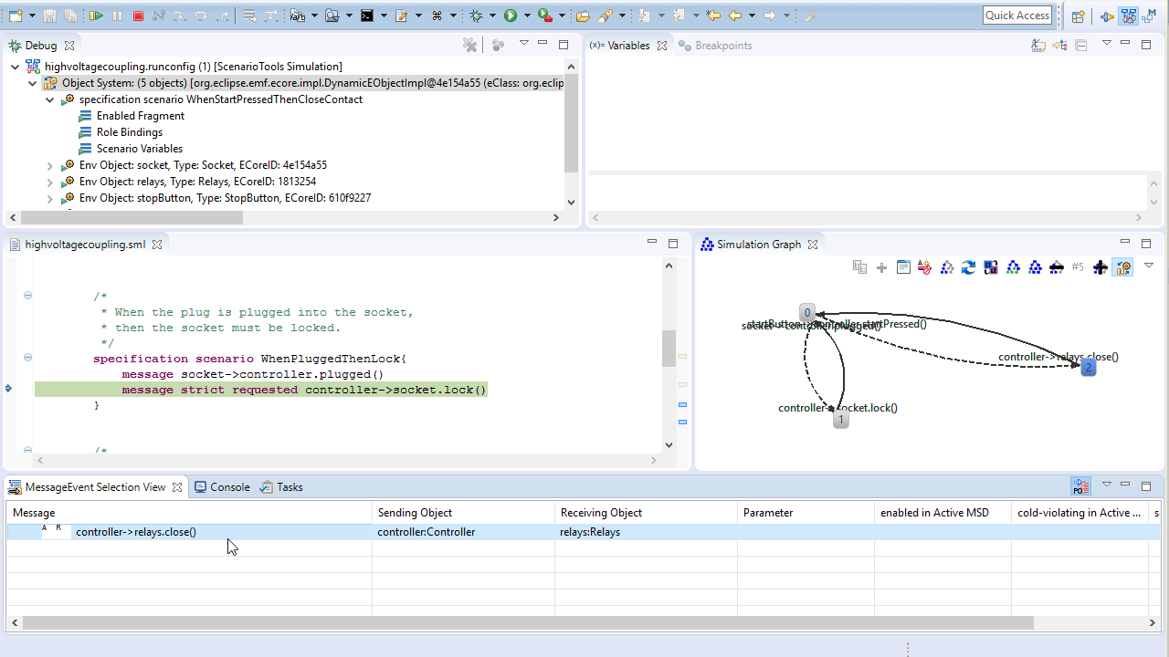
The first play-out simulation
There are mainly two cases we can play-out:
- From the initial state, we can execute the (environment) event
socket->controller.plugged(). This activates the scenarioWhenPluggedThenLock, which requestscontroller->socket.lock()to be sent. Then, sending this event terminates the scenario and we are again in the initial state. - From the initial state, we can execute the (environment) event
startButton->controller.startPressed(). This activates the scenarioWhenStartPressedThenCloseContact, which requestscontroller->relays.close()to be sent. Then, sending this event terminates the scenario and we are again in the initial state.
Obviously the specification seems incomplete and the behavior described by the scenarios seems unconnected. This will change shortly when we add further scenarios.
First realizability-checking via synthesis
We can also analyze the behavior via formal controller synthesis that performs a realizability checking by showing whether a strategy exists for the system to guarantee satisfaction of the specification in all possible environments.
The synthesis can be invoked as shown in the screenshot below
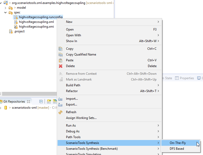
First synthesis run
The synthesis algorithm can successfully synthesize a strategy. We can visualize the state graph that was explored during the synthesis in a view. See the following screenshot
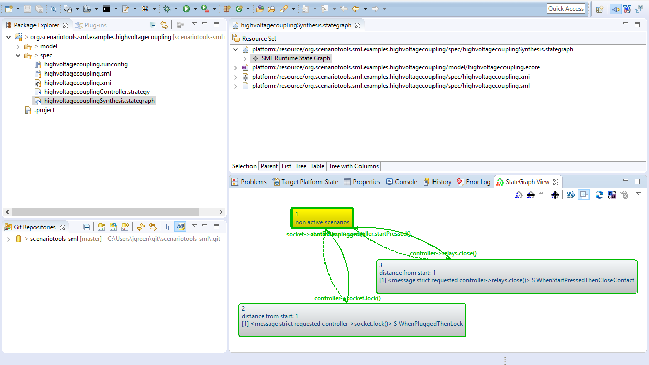
Result of first synthesis
Not surprisingly, the state graph looks similar to the graph that was visualized during the play-out simulation before. The states that are colored green are so-called winning states, from which the system can guarantee satisfying the specification.
Modeling the third requirement
Next, we turn to modeling requirement r3 (“When the plug is not plugged or not locked then the relays must not be closed”).
How should we model this requirement?
The requirement refers to the event of closing the relays, but also it refers to the state of the socket (plug plugged into the socket and socket locked). If we want to model this state information, we need to add variables that can store this information. The informal requirements do not mention these variables in detail, so we need to refine the requirements here. Let us deal with this issue first.
Adding state variables
When the controller is notified by the socket about a plug being plugged in, then it could store this information in a Boolean variable. We model this variable as a Boolean attribute of the controller object. Let’s call the attribute plugged. An attribute value of an object can be changed by sending set-messages to this object. But then we need to express that this set message must happen after the controller receives a plugged message from the socket. How do we do that?
We could add this refined requirement into the scenario WhenPluggedThenLock. Doing this, however, would bear the danger that a scenario that initially closely reflects the informal requirements gets cluttered with refined requirements. Another solution would be to separate this refined requirement into a separate scenario. We do this by the scenario SetPlugged (lines 32-35 in the listing below).
Similarly, we model the refined requirement that the controller should set another Boolean attribute, locked, to true after ordering the socket to lock (lines 36-40). Because this is a safety-critical system, we of course have to reflect whether we can really assume that the socket will be immediately and definitely locked when the controller tells the socket to lock. For the sake of simplicity, let’s say that we can make this assumption. (The careful engineer must validate this assumption and document it explicitly.)
Modeling an anti-scenario
Now we return to the question of how to model requirement r3 (“When the plug is not plugged or not locked then the relays must not be closed”).
In our scenario-based paradigm, a scenario starts with an event. Thus, one way to model the requirement is to turn it around and say “When the relays are closed, it must not be that the plug is not plugged in or the socket is not locked”. The corresponding scenario OnlyCloseRelaysWhenPlugPluggedAndLocked is shown in lines 51-60. If the condition of the violation is true when the scenario reaches this violation condition, then this is a violation of the specification scenario and therefore it is also a violation of the the specification.
import "../model/highvoltagecoupling.ecore"

system specification HighvoltagecouplingSpecification {

	domain highvoltagecoupling

	define Socket as uncontrollable
	define Relays as uncontrollable
	define StartButton as uncontrollable
	define StopButton as uncontrollable


	define Controller as controllable

	collaboration PlugAndStart {

		static role Socket socket
		static role Relays relays
		static role StartButton startButton
		static role Controller controller


		/*
		 * When the plug is plugged into the socket,
		 * then the socket must be locked.
		 */
		specification scenario WhenPluggedThenLock{
			message socket->controller.plugged()
			message strict requested controller->socket.lock()
		}

		specification scenario SetPlugged{
			message socket->controller.plugged()
			message strict requested controller->controller.setPlugged(true)
		}

		specification scenario SetLocked{
			message controller->socket.lock()
			message strict requested controller->controller.setSocketLocked(true)
		}

		/*
		 * When the start-button is pressed,
		 * then the relays have to be closed.
		 */
		specification scenario WhenStartPressedThenCloseContact{
			message startButton->controller.startPressed()
			message strict requested controller->relays.close()
		}

		/*
		 * When the plug is not plugged or not
		 * locked then the relays must not be closed.
		 * -> Modeled as an anti-scenario: closing the relays
		 *    leads to a violation if not plugged or not locked
		 */
		specification scenario OnlyCloseRelaysWhenPlugPluggedAndLocked {
			message controller->relays.close()
			violation if [!controller.plugged | !controller.socketLocked]
		}

	}

}
Re-run realizability checking to find the first problem
When we re-run realizability checking for the extended specification, we find a problem. Using the state graph view, we can see that after pressing the start button, the relays will be closed, but this leads to a violation in the scenario OnlyCloseRelaysWhenPlugPluggedAndLocked. This is what we expected, since there is not yet any plug plugged in nor locked.
The question is why the relays are closed? This happens because the scenario WhenStartPressedThenCloseContact requests the relays to be closed after start was pressed.
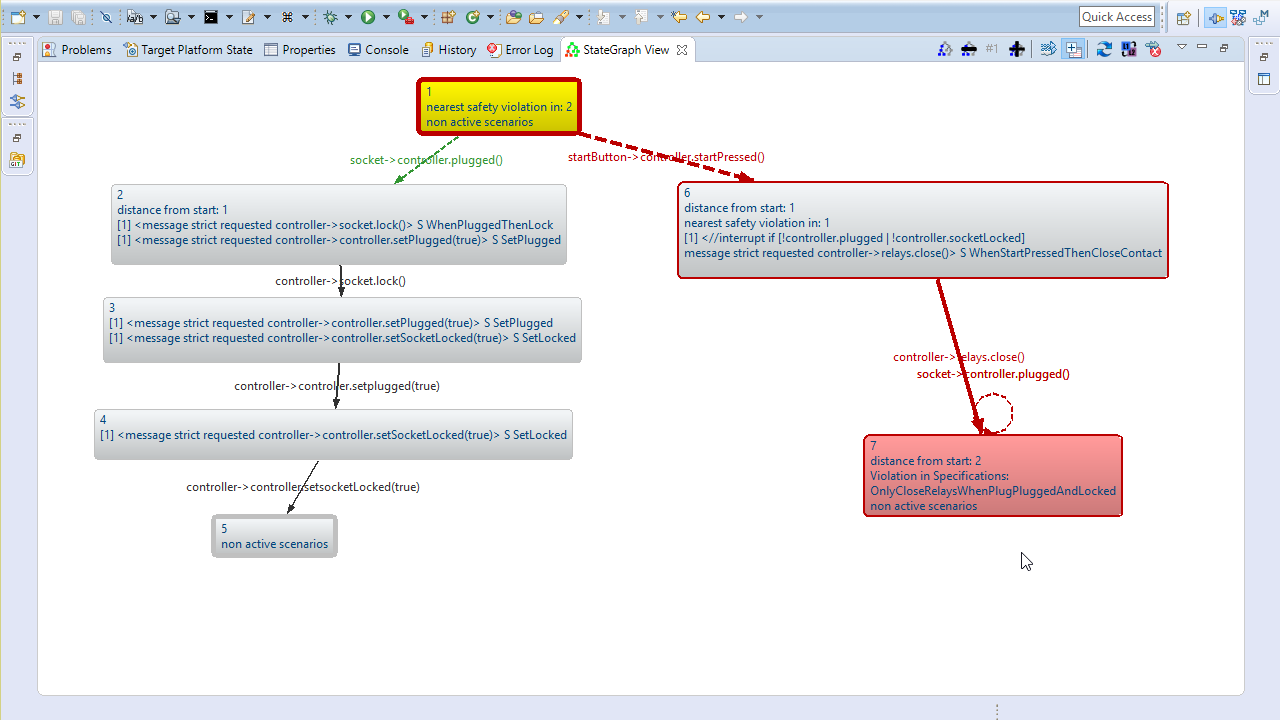
Result of re-running realizability checking after modeling requirement r3
Here we have found an inconsistency in the requirements. Requirement r2 requires the relays to close unconditionally after start was pressed, but requirement r3 formulates a condition under which this must not happen.
This could be a case of implicit priorities: Let’s consider that we face the stakeholders with this problem and we get the answer “Well, what I meant to say is that r2 is the default behavior and r3 should be an exception to that default”. This relationship between the requirements is not clear, and should be made explicit.
Fixing the inconsistency
One way of making the implicit relationship between r2 and r3 explicit is to add an exception condition for r2.
We formulate an updated version of the requirement, r2a:
| No. | Requirement name | Requirement Text |
| r2a
(replaces r2) |
start-button pressed | When the start button is pressed, then the relays have to be closed unless the plug is not plugged or not locked. |
In the SML specification, we add this exception as an interrupt condition, which terminates the active scenario when it gets enabled, but the condition expression evaluates to false.
import "../model/highvoltagecoupling.ecore"

system specification HighvoltagecouplingSpecification {

	domain highvoltagecoupling

	define Socket as uncontrollable
	define Relays as uncontrollable
	define StartButton as uncontrollable
	define StopButton as uncontrollable


	define Controller as controllable

	collaboration PlugAndStart {

		static role Socket socket
		static role Relays relays
		static role StartButton startButton
		static role Controller controller


		/*
		 * When the plug is plugged into the socket,
		 * then the socket must be locked.
		 */
		specification scenario WhenPluggedThenLock{
			message socket->controller.plugged()
			message strict requested controller->socket.lock()
		}

		specification scenario SetPlugged{
			message socket->controller.plugged()
			message strict requested controller->controller.setPlugged(true)
		}

		specification scenario SetLocked{
			message controller->socket.lock()
			message strict requested controller->controller.setSocketLocked(true)
		}

		/*
		 * When the start-button is pressed,
		 * then the relays have to be closed.
		 */
		specification scenario WhenStartPressedThenCloseContact{
			message startButton->controller.startPressed()
			interrupt if [!controller.plugged | !controller.socketLocked]
			message strict requested controller->relays.close()
		}

		/*
		 * When the plug is not plugged or not
		 * locked then the relays must not be closed.
		 * -> Modeled as an anti-scenario: closing the relays
		 *    leads to a violation if not plugged or not locked
		 */
		specification scenario OnlyCloseRelaysWhenPlugPluggedAndLocked {
			message controller->relays.close()
			violation if [!controller.plugged | !controller.socketLocked]
		}

	}

}
When we again run realizability checking for the specification, we see that the specification is now realizable. The state graph view shows us the winning states:
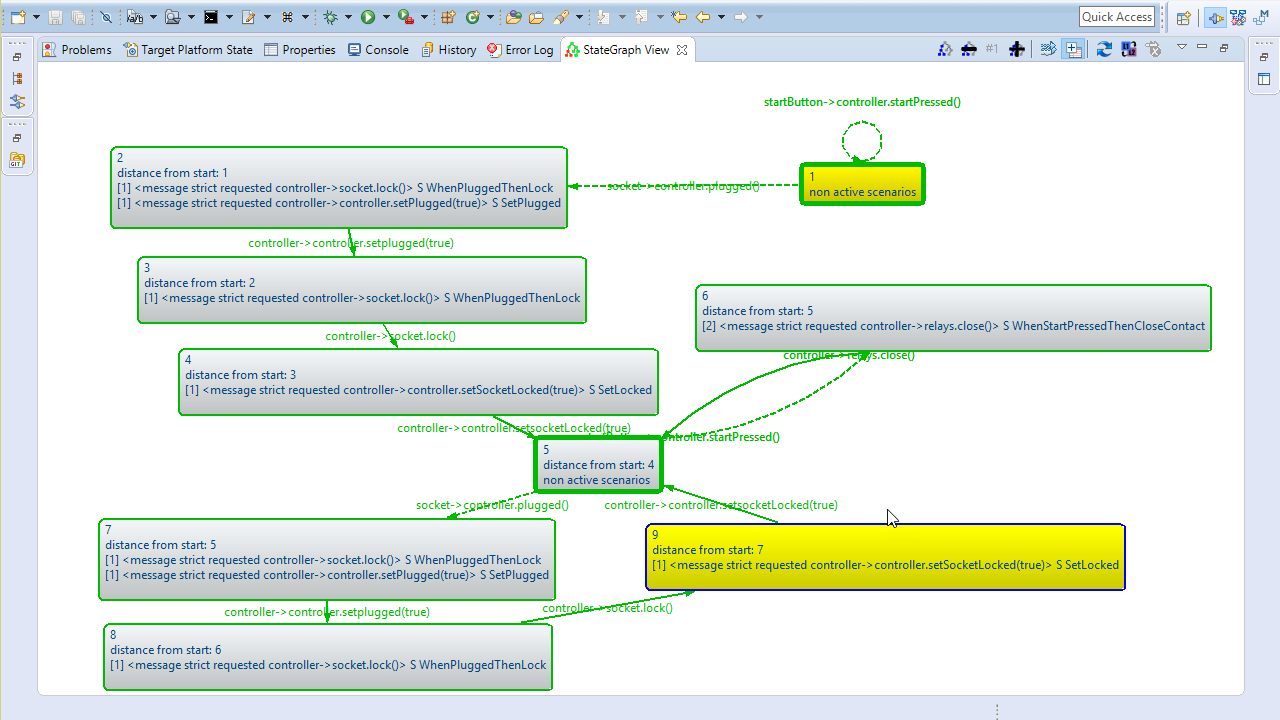
Synthesis result after changing r2
Among other things, we see that pressing start without a previous plugged-in event leads to a self-transition in the initial state, i.e., it is ignored. Pressing start after plugging in and locking the socket (in state 5) leads to closing the relays (state 6).
We also see that in state 5, that the state graph considers the case that another plugged event occurs, and, subsequently, another lock event follows as required by r1. It seems strange that a plugged event can occur although a plug is already plugged in. We keep in mind to clarify this with the other stakeholders, but so far, it does not seem to cause any conflicts with the other requirements.
Modeling the fourth requirement
We now turn to modeling requirement r4 (“When the relays are closed, the plug must not be unplugged.”). We model this requirement as an anti-scenario as before. Because this requirement also refers to the state of the relays, we add the Boolean attribute relaysClosed to the controller, along with a scenario responsible for setting this attribute to true after the controller orders the relays to close. The listing below shows the scenarios that we have so far, highlight the extension that comes with modeling requirement r4.
import "../model/highvoltagecoupling.ecore"

system specification HighvoltagecouplingSpecification {

	domain highvoltagecoupling

	define Socket as uncontrollable
	define Relays as uncontrollable
	define StartButton as uncontrollable
	define StopButton as uncontrollable


	define Controller as controllable

	collaboration PlugAndStart {

		static role Socket socket
		static role Relays relays
		static role StartButton startButton
		static role Controller controller


		/*
		 * When the plug is plugged into the socket,
		 * then the socket must be locked.
		 */
		specification scenario WhenPluggedThenLock{
			message socket->controller.plugged()
			message strict requested controller->socket.lock()
		}

		specification scenario SetPlugged{
			message socket->controller.plugged()
			message strict requested controller->controller.setPlugged(true)
		}

		specification scenario SetLocked{
			message controller->socket.lock()
			message strict requested controller->controller.setSocketLocked(true)
		}

		/*
		 * When the start-button is pressed,
		 * then the relays have to be closed.
		 */
		specification scenario WhenStartPressedThenCloseContact{
			message startButton->controller.startPressed()
			interrupt if [!controller.plugged | !controller.socketLocked]
			message strict requested controller->relays.close()
		}

		/*
		 * When the plug is not plugged or not
		 * locked then the relays must not be closed.
		 * -> Modeled as an anti-scenario: closing the relays
		 *    leads to a violation if not plugged or not locked
		 */
		specification scenario OnlyCloseRelaysWhenPlugPluggedAndLocked {
			message controller->relays.close()
			violation if [!controller.plugged | !controller.socketLocked]
		}

		specification scenario SetRelaysClosed{
			message controller->relays.close()
			message strict requested controller->controller.setRelaysClosed(true)
		}

		/*
		 * When the relays are closed, the plug
		 * must not be unplugged.
		 */
		specification scenario UnplugForbiddenWhenRelaysClosed {
			message socket->controller.unplugged()
			violation if [controller.relaysClosed]
		}

	}

}
Re-run realizability checking to find the next problem
Again, we re-run the realizability checking procedure and find another problem. This time, a violation occurs after 8 steps. In order to create a simpler view, we switch the state graph view into a mode where it condenses each super-step into only one transition arrow. (A super-step is a sequence of events starting with an environment event and then a sequence of system events in reaction to that environment event, until the system waits for the next environment event. The condensed view gives a better overview.)
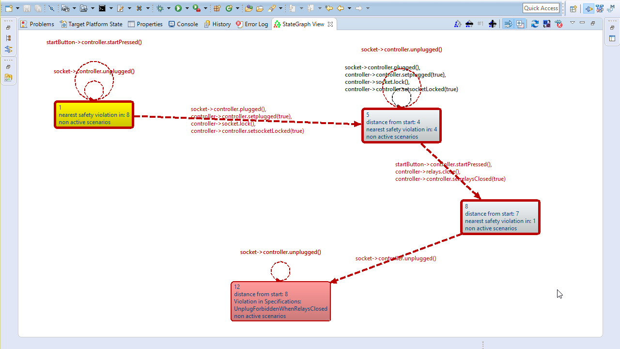
The problem is now after plugging in, locking the socket, pressing start, and closing the relays, an unlock happens, which violates the newly added scenario UnplugForbiddenWhenRelaysClosed.
But how can this be? We just locked the socket so that the plug cannot be pulled from the socket!
The problem is that this an implicit assumption, and since it is not modeled explicitly in the SML specification, this assumption is not considered by the realizability checking procedure. The problem with such implicit assumptions is not only that no algorithm can guess them automatically. Even worse, if a specification of a critical system contains implicit assumptions, it is possible that they are never discussed and, most importantly validated. In this example, maybe it is important to consider the case that a user can, with sufficient force, pull the plug from the locked socket. Then we may have to think about emergency shutdown procedures.
Let us consider the case that it is valid to assume that the plug cannot be pulled when the socket is locked. One way to model this would be to use an assumption anti-scenario that says that it is forbidden (for the environment) to have unplug occur when the relay is closed. This could be modeled as shown below. The problem with this way of modeling is, however, that an assumption about the possible behavior of the environment depends on a variable of the software controller. See the highlighted line below.
import "../model/highvoltagecoupling.ecore"

system specification HighvoltagecouplingSpecification {

	domain highvoltagecoupling

	define Socket as uncontrollable
	define Relays as uncontrollable
	define StartButton as uncontrollable
	define StopButton as uncontrollable


	define Controller as controllable

	collaboration PlugAndStart {

		static role Socket socket
		static role Relays relays
		static role StartButton startButton
		static role Controller controller


		/*
		 * When the plug is plugged into the socket,
		 * then the socket must be locked.
		 */
		specification scenario WhenPluggedThenLock{
			message socket->controller.plugged()
			message strict requested controller->socket.lock()
		}

		specification scenario SetPlugged{
			message socket->controller.plugged()
			message strict requested controller->controller.setPlugged(true)
		}

		specification scenario SetLocked{
			message controller->socket.lock()
			message strict requested controller->controller.setSocketLocked(true)
		}

		/*
		 * When the start-button is pressed,
		 * then the relays have to be closed.
		 */
		specification scenario WhenStartPressedThenCloseContact{
			message startButton->controller.startPressed()
			interrupt if [!controller.plugged | !controller.socketLocked]
			message strict requested controller->relays.close()
		}

		/*
		 * When the plug is not plugged or not
		 * locked then the relays must not be closed.
		 * -> Modeled as an anti-scenario: closing the relays
		 *    leads to a violation if not plugged or not locked
		 */
		specification scenario OnlyCloseRelaysWhenPlugPluggedAndLocked {
			message controller->relays.close()
			violation if [!controller.plugged | !controller.socketLocked]
		}

		specification scenario SetRelaysClosed{
			message controller->relays.close()
			message strict requested controller->controller.setRelaysClosed(true)
		}

		/*
		 * When the relays are closed, the plug
		 * must not be unplugged.
		 */
		specification scenario UnplugForbiddenWhenRelaysClosed {
			message socket->controller.unplugged()
			violation if [controller.relaysClosed]
		}

		assumption scenario NoUnplugWhenLocked{
			message socket->controller.unplugged()
			violation if [controller.relaysClosed]
		}

	}

}
An alternative could be to introduce a state variable about the locked/unlocked state of the physical lock as an attribute of the socket (instead of using the controllers variable, which is merely the software representation of the environment state). However, this would need extra scenarios for setting the values of this environment state variable.
Instead, we can add a scenario that says that between a lock and unlock event, there cannot be an unplug event. This way, we refer to events that are also observable in the environment. (The rationale is that the controller sends the lock and unlock events to the socket, where they lead, physical, immediately to the closing resp. opening of the lock. If this effect is not direct, because for example locking takes non-neglible time or the lock can be blocked by dirt, then of course also a more elaborate model of the environment must be created, and also ways for the software to safely deal with such intricate effects and faults in the mechanical hardware.)
The following listing shows the SML specification in full, highlighting the new assumption scenario.
import "../model/highvoltagecoupling.ecore"

system specification HighvoltagecouplingSpecification {

	domain highvoltagecoupling

	define Socket as uncontrollable
	define Relays as uncontrollable
	define StartButton as uncontrollable
	define StopButton as uncontrollable


	define Controller as controllable

	collaboration PlugAndStart {

		static role Socket socket
		static role Relays relays
		static role StartButton startButton
		static role Controller controller


		/*
		 * When the plug is plugged into the socket,
		 * then the socket must be locked.
		 */
		specification scenario WhenPluggedThenLock{
			message socket->controller.plugged()
			message strict requested controller->socket.lock()
		}

		specification scenario SetPlugged{
			message socket->controller.plugged()
			message strict requested controller->controller.setPlugged(true)
		}

		specification scenario SetLocked{
			message controller->socket.lock()
			message strict requested controller->controller.setSocketLocked(true)
		}

		/*
		 * When the start-button is pressed,
		 * then the relays have to be closed.
		 */
		specification scenario WhenStartPressedThenCloseContact{
			message startButton->controller.startPressed()
			interrupt if [!controller.plugged | !controller.socketLocked]
			message strict requested controller->relays.close()
		}

		/*
		 * When the plug is not plugged or not
		 * locked then the relays must not be closed.
		 * -> Modeled as an anti-scenario: closing the relays
		 *    leads to a violation if not plugged or not locked
		 */
		specification scenario OnlyCloseRelaysWhenPlugPluggedAndLocked {
			message controller->relays.close()
			violation if [!controller.plugged | !controller.socketLocked]
		}

		specification scenario SetRelaysClosed{
			message controller->relays.close()
			message strict requested controller->controller.setRelaysClosed(true)
		}

		/*
		 * When the relays are closed, the plug
		 * must not be unplugged.
		 */
		specification scenario UnplugForbiddenWhenRelaysClosed {
			message socket->controller.unplugged()
			violation if [controller.relaysClosed]
		}

		assumption scenario NoUnplugBetweenLockAndUnlock{
			message controller->socket.lock()
			message controller->socket.unlock()
		}constraints[
			forbidden message socket->controller.unplugged()
		]

	}

}
Re-run realizability checking
Next, we again re-run the realizability checking to make sure that there are no inconsistencies. And indeed, this time it looks good. The following screenshot of the state graph view shows the state graph with condensed super-steps.
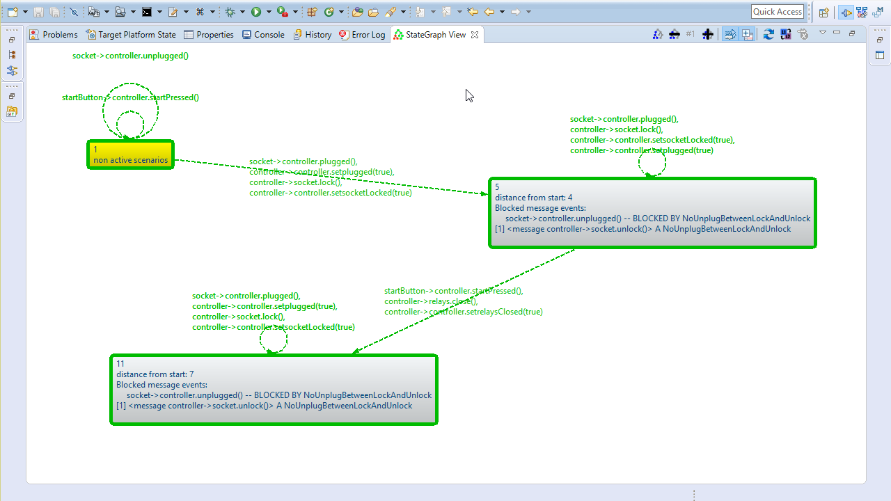
Synthesis result after adding assumption “NoUnplugBetweenLockAndUnlock”
What is missing now is obviously specifying the behavior for stopping and unplugging a consumer from the HVCS.
Visit our tutorial at the MODELS 2016 conference to learn about the next steps.